

Begin by matching the pinout before any splice goes in. Two wires power the heater, and two carry the signal, so one wrong connection can leave the PCM guessing while the engine runs rough and rich.
This walkthrough covers connector matching, heater checks, live voltage readings, and wiring faults on Bosch, Denso, NTK, and other OBD-II systems for anyone dealing with a replacement sensor or a no-read fault.
Four-Wire Sensor Basics And Wire Identification
That split keeps the reading stable, because the heater and sensing circuits do different jobs. Two wires warm the element fast enough for usable output, while the other two carry the signal and its ground path.
Wire colors are not universal. One Bosch sensor can use a different color set than a Denso or NTK unit, so the connector chart or vehicle service data matters more than jacket color.
Heater wires and signal wires serve different jobs
The heater circuit powers a small internal element that brings the zirconia tip up to operating temperature. The signal pair carries the sensor output that shifts with exhaust oxygen content and fuel mixture, which the ECM or PCM uses for fuel trim control.
Narrowband sensors and wideband sensors do not read the same way. A narrowband unit swings around a switching point, while a wideband design uses a different internal layout and wiring strategy, so the vehicle-specific diagram is the only safe starting point for wideband vs narrowband O2 sensor wiring.
Color alone can send you down the wrong path
Black, gray, white, and blue wires show up in different combinations, but harness order matters more than shade. A sensor can look right on the bench and still be wrong at the connector if the signal ground and heater supply land on the wrong pins.
That mistake shows up fast as a fault code, a dead heater, or a signal trace that sits flat. Once the wire roles are known, the next step is reading the pinout before any splice touches the harness.
With the wire roles identified, the harness can be matched against the diagram before any splice is made.
Reading The Pinout Before Any Splicing Or Installation
So the 4 wire oxygen sensor wiring diagram is the map for heater power, heater ground or control, signal, and signal ground. That order belongs in hand before the harness gets cut or crimped.
Aftermarket connectors can use color sets that look familiar but land the circuits differently. Matching color to color is how a lot of clean-looking repairs turn into repeat diagnostic trouble code returns.
Match connector cavities to the vehicle harness
Start with the connector face, not the wire bundle. The pinout on the sensor side and the harness side must line up by circuit function, because one reversed heater lead can keep the element cold while the signal circuit still looks intact.
Factory diagrams from the vehicle maker, plus service information for the specific engine code, give the pin order and the expected ground path. That matters on Toyota, Ford, GM, Honda, Subaru, and Volkswagen setups, because each can place the heater control on a different side of the circuit.
Do not trust aftermarket color conventions
Universal pigtails from Walker, Standard Motor Products, and similar parts makers save time, but their colors are only a guide. The same white-white pair can be heater power on one pigtail and heater control on another, so each terminal still needs verification.
Think in terms of circuits, not paint. Once the pinout is mapped, the heater circuit test is next, and that tells whether the sensor can warm up at all.
That mapping sets up a heater test, where a multimeter reveals whether the sensor can warm up properly.
Testing The Heater Circuit With A Multimeter
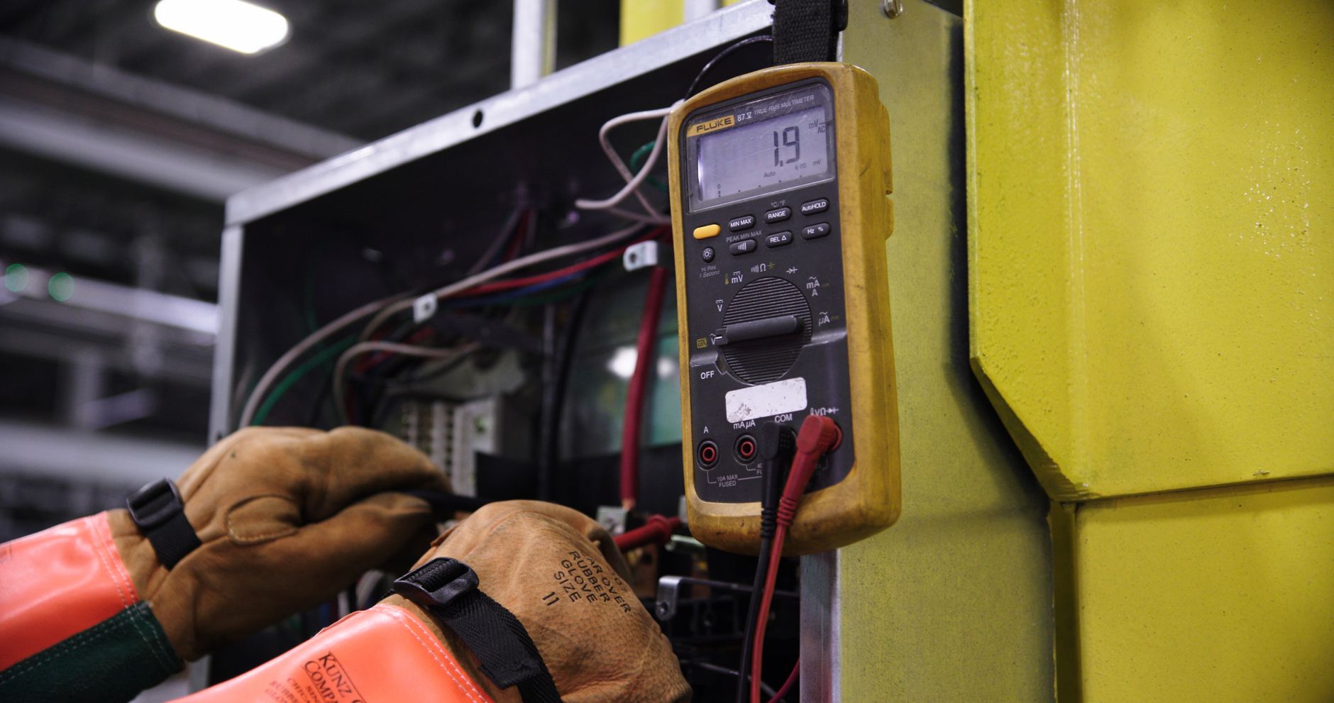
A cold sensor can act dead on the scan tool even though the signal element is fine. The heater circuit is the first place to look, and a multimeter gives three useful checks: resistance, continuity, and supplied voltage.
Heater wires often show low resistance, which is normal for a small resistive element. A reading that sits open, or one that is far outside the service spec, points to a failed heater or a broken path in the harness.
Measure resistance across the heater pair
Set the meter to ohms and probe the two heater pins on the sensor side. A healthy element often lands in a low resistance range, while an open circuit means the internal heater coil is broken.
Do not guess from appearance. A sensor shell can look new and still have a burned heater after a long period of rich running, oil contamination, or repeated short trips that never let the exhaust get hot.
Check continuity from the heater pins to the harness
Using a multimeter, check continuity from each heater terminal into the harness and toward the control side or ground path. That step finds broken strands, stretched wires near the exhaust, and corroded pins that block current.
A continuity beep with high resistance still matters, because a weak connection can pass a meter check yet fail under load. The wire can test fine until the insulation is flexed beside the downpipe, where heat and vibration expose the fault.
Confirm battery voltage at the heater feed
Key on, engine off is the cleanest voltage check for the feed side. You want battery voltage reaching the heater supply, with the control side providing a solid ground or PCM-controlled path depending on the system.
That is the real O2 sensor heater circuit test. If voltage is missing, chase the fuse, relay, splice, or ground before replacing the sensor, because a fresh part cannot heat without power.
A missing reading there often points upstream, where power delivery must be traced before the sensor gets blamed.
Tip: Backprobe the connector instead of piercing wire insulation. You keep the seal intact and get a cleaner reading at the same time.
Checking The Signal Circuit And Live Voltage Response
Once the heater path checks out, the signal side tells whether the sensing element still reacts to exhaust changes. A narrowband sensor should switch between lean and rich conditions, and that movement is what the OBD-II monitor uses for fuel control.
On a healthy narrowband sensor, voltage fluctuation is part of the pattern. A flat line, a stuck high reading, or a lazy sweep can point to wiring damage, contamination, or a tired sensor.
Watch the switching pattern on a scan tool
Warm the engine fully, then view live data while the ECM trims fuel. On many narrowband systems, the signal should move rapidly as the mixture shifts, not sit frozen near one number.
You can induce a change with a brief vacuum leak, a quick throttle snap, or a controlled rich condition from a small propane enrichment tool. The sensor should answer that change within moments, not after a long delay.
Use the multimeter for an oxygen sensor voltage test
A digital multimeter can show the basic shape of the signal, even if a scan tool gives the cleaner view. Backprobe the signal wire and watch the voltage response as the engine mixture moves from lean to rich.
For a narrowband sensor, the output usually crosses back and forth across the switching point instead of rising smoothly like a thermometer. Wideband units work differently, so a flat reading on the meter does not mean the same thing on every system.
Separate wiring faults from sensor failure
A stuck reading can come from a bad ground, a damaged signal wire, or exhaust contamination from coolant, silicone, or oil ash. The sensor tip lives in harsh exhaust gas, so the reading reflects both the element and the path around it.
That distinction matters. A sensor that never changes under mixture shifts is not always bad, but the circuit must prove itself before the part gets replaced.
When the signal stays stubbornly unchanged, the fault may lie in heater control, wiring, or even the exhaust itself.
| Reading pattern | Likely cause | What you check next |
|---|---|---|
| Flat low voltage | Open signal path or lean condition | Ground, signal wire, exhaust leak |
| Flat high voltage | Rich mixture or short to power | Fuel trim data, connector, harness |
| Slow switching | Lazy sensor or heater issue | Heater power, contamination, response speed |
| No response | Bad wiring or failed element | Continuity, resistance, scan tool data |
Faults That Point To Heater, Wiring, Or Exhaust Problems
Slow warm-up is the classic heater complaint. The engine stays in open loop longer than it should, fuel trim stays less stable, and the PCM may set a code tied to heater performance or sensor response.
Damaged wiring near the exhaust, poor grounds, and corroded connectors are the failures that show up most often in real service work. Heat hardens insulation, road splash eats terminals, and vibration breaks copper strands right where the harness bends.
Heater faults show up as delayed activity
A bad heater circuit can mimic a dead sensor for the first minute or two after startup. On a cold morning, the scan tool may show little activity, then the signal wakes up late, which is a clue that the element cannot reach operating temperature fast enough.
That delay matters because the ECM depends on a warmed sensor to switch closed-loop fueling. A long delay can trigger a diagnostic trouble code even before drivability feels rough.
Harness damage and corrosion break the circuit
Look closely at the pigtail where it crosses the transaxle, the firewall, or the exhaust tunnel. A single green terminal or cracked insulation sleeve can interrupt current far more than the sensor itself.
Corrosion raises resistance, and resistance steals heater current. The result is a weak element, slow signal switching, and a repair that keeps coming back unless the connector body and terminals are cleaned or replaced.
Exhaust leaks and contamination distort the reading
Small leaks upstream of the sensor pull outside air into the stream and make the mixture look lean. Oil burning, coolant entry, and silicone contamination coat the sensing tip and slow the chemistry at the surface.
Here is the deeper mechanism: a zirconia sensor makes voltage from the oxygen difference between exhaust gas and outside air, and contamination blocks that diffusion path. Once the surface is coated, the signal can drift even though the wiring still passes every ohm check.
- Slow closed-loop entry Heater power or ground is weak, so the sensor wakes up late.
- Repeated heater codes Current never reaches the element at the expected level.
- Stuck lean reading Exhaust leak or broken signal path pulls the value low.
- Stuck rich reading Shorted wiring or fuel contamination can hold the output high.
- Intermittent signal Vibration or corrosion opens the circuit under load.
Once symptoms are separated from causes, installation becomes a finishing step instead of a guess. That is where the final pinout check and live verification come in.
Once those causes are separated, fitting the sensor correctly becomes a final check rather than an uncertain fix.
Installing The Sensor And Verifying The Repair
The last wiring check belongs at the connector, with the harness routed clear of the exhaust and clipped so it cannot rub. A melted lead near the converter can undo an otherwise clean repair in a week.
Before sealing the loom, confirm that each pin lands in the right cavity and that the ground wire, signal wire, and heater feed all match the vehicle diagram. That final look is the difference between a clean start and a repeat repair.
Clear codes and watch a fresh warm-up cycle
After assembly, clear the stored codes and start the engine cold. Then watch heater current, signal response, and closed-loop entry on the scan tool as the engine warms.
A good repair shows battery voltage at the heater, stable continuity through the connector, and a live signal that changes with exhaust oxygen content. That combination is the real proof that the circuit works, not the look of the part in your hand.
Run one more live voltage check after road use
Take the vehicle through a short drive and recheck the data with the engine fully hot. A sensor that responds in the bay but fails under road heat points back to harness strain, exhaust leak, or a control issue in the PCM path.
How to wire and test a 4 wire O2 sensor comes down to the same sequence every time: match the pinout, verify heater power, and confirm real-time signal swing. Miss one of those, and the result is guesswork instead of a repair.
The repair only holds when pinout, heater power, and live signal swing all line up as expected.
What To Remember
The pinout decides everything. A four-wire sensor only works as intended when the heater pair, signal pair, battery feed, and ground or control path land in the right order, and the live voltage response proves the circuit is alive.
FAQ
What are the wires on a 4 wire O2 sensor?
Two wires belong to the heater circuit, and two wires belong to the signal circuit. The exact colors vary by Bosch, Denso, NTK, and vehicle application, so the connector diagram matters more than the insulation color.
How do you test a 4 wire oxygen sensor with a multimeter?
Check heater resistance across the heater pair, then verify continuity through the harness and battery voltage at the heater feed with the key on. After that, backprobe the signal wire and watch for voltage fluctuation as mixture changes.
How do you identify the heater wires on an O2 sensor?
The heater wires are the pair that shows low resistance on an ohmmeter and ties into battery power plus a ground or control path. Service data for the vehicle pinout is the safest way to confirm them before any splice or replacement.
What voltage should an O2 sensor read?
A narrowband sensor normally switches voltage between lean and rich conditions rather than holding one fixed number. The exact range depends on the system, but a flat reading or a slow response points to wiring trouble, contamination, or sensor failure.
Can you wire a 4 wire O2 sensor backwards?
Yes, and the result can be a dead heater, a bad signal, or a stored fault code. The connector must follow the vehicle pinout, not the color guess, because the circuits need the correct order to work.