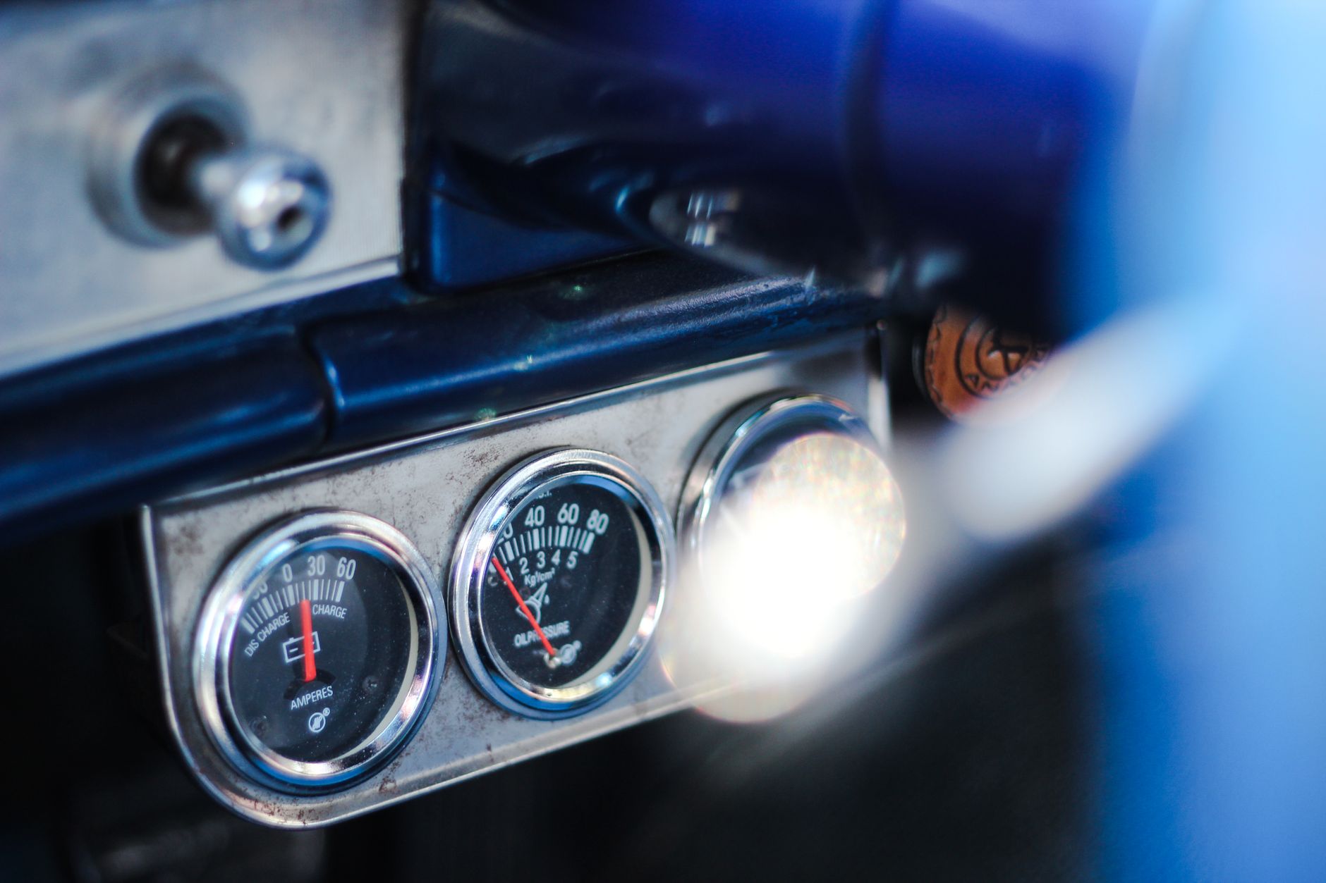

A simple on-off warning device is compared with a variable sender that tracks pressure changes. One usually flips a light at a set threshold, while the other can feed a gauge or ECU with a range of readings.
Here’s a practical breakdown for anyone replacing a part on a Ford, GM, Toyota, or similar vehicle, including how the circuit works and what the dash is really telling you.
Two Parts, Two Very Different Jobs
A sensor measures pressure across a range, which is why one engine may use a switch for the warning lamp and a sensor for the gauge.
The switch acts like a gate
Spring tension and oil pressure fight each other inside the switch. At low pressure, the contacts stay in one state and the warning light comes on. Once pressure reaches the set point, the contacts flip and the light goes out.
That setup works because the circuit only needs a yes-or-no answer. It cannot tell the difference between 18 psi at idle and 62 psi at cruise, but it can warn you fast when pressure falls below safe range.
The sensor behaves like a variable sender
A sensor uses variable resistance, a piezoresistive element, or another transducer to change its output as pressure changes. The ECU or dash gauge reads that signal and turns it into a needle position, a data value, or a warning strategy.
GM and Toyota systems often use that signal for both the instrument cluster and engine control logic. Ford setups can do the same, but the wiring and calibration depend on the year and engine family. That is why the circuit matters more than the label on the box.
Some vehicles use one combined sending unit
A combined oil pressure sending unit handles both jobs in one housing. One internal path can feed the warning lamp, while another sends a gauge signal, so a single threaded port does the work of two parts.
That design shows up in trucks, older domestic cars, and some late-model engines with simplified clusters. The housing may look ordinary, but the internal calibration can split lamp logic from gauge output. That setup leads straight into the next question: where each part fits in the vehicle.
That split in function raises a practical question about where each piece actually lives in the car.
Where Each Part Fits In The Vehicle
That wiring decision shows up at the dashboard first. A warning lamp circuit and a gauge circuit solve different problems, so the factory chooses the part that matches the cluster design. A lamp wants a hard trigger. A gauge wants a stable range. The Engine Control Unit may want both.
Switches suit warning lamps
In a simple setup, the switch feeds an oil pressure warning light that only cares about low pressure. A cold start, a worn bearing, or a clogged pickup can drop pressure far enough to trip that lamp, and the circuit gives an immediate alert.
That setup works well on older engines and some budget trims because the instrument cluster does not need a number. It only needs a red light that reacts fast enough to keep you from driving with low oil pressure.
Sensors feed gauges and control logic
A sensor becomes useful when the dash shows a needle or digital reading. The ECU can also watch that signal and compare it with rpm, oil temperature, and load to sort a real fault from a brief idle dip.
OBD-II systems can store codes such as P0520, P0521, P0522, P0523, or P0524 when the pressure signal falls outside expected behavior. That matters because a bad signal can set a code even while the engine still has healthy lubrication, and you need that distinction before you start swapping parts.
The factory design decides the correct part
Year, engine, cluster type, and harness layout decide whether you need a switch, a sensor, or a dual-function sender. A vehicle with only a warning lamp has no reason to carry a variable gauge sender, and a car with a live dash reading needs a component that can report a range.
That is why the difference between oil pressure switch and sensor starts at the wiring diagram, not at the parts counter. Once the system layout is clear, the symptoms make much more sense. The failure clues are the next place to look.
With the layout mapped, the warning signs become easier to separate from ordinary wear.
Reading The Symptoms Of A Failing Unit
A bad sender can act dramatic without any real engine damage behind it. The trick is separating part failure from low oil pressure, wiring trouble, or a blocked passage. That separation keeps you from replacing the wrong component and missing the real fault.
Switch problems show up at the warning light
Oil pressure switch symptoms often start with a flickering lamp at hot idle or a warning that comes and goes over bumps. Corroded terminals can make the light behave like a loose door latch, flashing even though the pressure itself has not collapsed.
A switch that sticks can also keep the light on after startup. In that case, the contacts do not change state cleanly, so the dash says the engine is in trouble even though the actual reading may still be acceptable.
Sensor problems distort the gauge
Oil pressure sensor symptoms usually involve a pegged needle, a dead gauge, or readings that jump around with no pattern. A signal wire with a bad ground can make the dash think pressure is zero, while an open circuit can send the gauge to full scale on some cluster designs.
On scan data, the ECU may report a value that does not match the mechanical reality. A scan tool reading of 0 psi at hot idle can be a wiring fault, a sensor fault, or genuine low oil pressure, so the next step depends on how the signal behaves at the connector.
Other faults can mimic part failure
Low oil level, sludge, a worn pump, and a blocked oil gallery can all imitate a bad switch or sensor. A pressure port packed with varnish gives the sender stale information, so the part looks guilty when the passage is the real problem.
A quick visual check helps before any replacement. Look for oil seepage at the housing, damaged insulation near the connector, and loose pins at the plug. Those small issues can create a false alarm that feels like a major failure.
Tiny connector faults can masquerade as major failures, which is why the test method matters.
- Check oil level: Low oil can make the lamp or gauge act erratically before the sender is at fault.
- Inspect the connector: Bent pins and oil-soaked terminals can break the electrical signal.
- Watch hot idle: A pattern that appears only warm points toward pressure, not just wiring.
- Compare data: Scan tool readings and dash behavior should tell the same story.
Testing A Switch Versus Testing A Sensor
Bench checks work differently because the two parts speak different electrical languages. A switch is judged by continuity, while a sensor is judged by signal output, resistance change, or voltage change as pressure changes.
Continuity testing fits a switch
A switch should show an open or closed circuit depending on the pressure state and the service specification. With the engine off, many designs read one way; with pressure applied, they flip to the other. A multimeter set to continuity or ohms makes that change easy to see.
The exact behavior depends on the design, so the service data matters. Some switches ground the lamp circuit at low pressure, while others feed battery voltage through the switch body. That is why a generic continuity check can mislead you unless you know the expected state for your engine.
Signal output testing fits a sensor
A sensor should change voltage or resistance in a smooth, repeatable way as pressure changes. A dead-flat reading across a wide range points to a fault in the sensor, wiring, or reference supply rather than healthy operation.
GM oil pressure senders often use a specific resistance curve, and many Toyota systems route the signal through the ECU before the cluster displays it. You get the cleanest result by comparing the measured value with the factory chart for that exact engine, not with a generic parts-store guess.
Specs matter more than assumptions
Engine oil pressure is not a single universal number, and sender calibration is not universal either. A 4.3L GM V6, a Ford Modular V8, and a Toyota four-cylinder can use different threshold points and different signal ranges even when the threads look the same.
That is where a service manual, wiring diagram, or OEM catalog entry becomes the deciding tool. The right part can still fail, but the wrong test order wastes time and turns a simple diagnosis into a guessing game. It also explains why the same symptom can point to different parts on different vehicles.
A wrong assumption here wastes time and turns diagnosis into guesswork across different vehicles.
| Check | Oil pressure switch | Oil pressure sensor |
|---|---|---|
| Electrical behavior | On or off at a set threshold | Changes output across a range |
| Common use | Oil warning light | Dash gauge or ECU input |
| Basic test | Continuity or circuit state | Voltage, resistance, or scan data |
| Failure clue | Flicker, false lamp, stuck lamp | Pegged, dead, or jumpy gauge |
Choosing The Correct Replacement Part
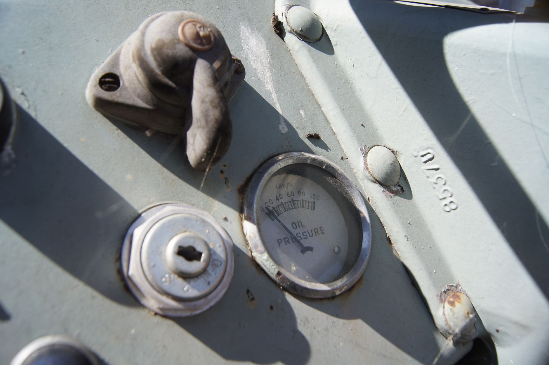
The correct replacement matches the vehicle, not just the thread size or connector shape. A part can screw into the block and still send the wrong signal to the dash, which leaves you with a working connector and a useless reading.
Match year, engine, and dash setup
Start with the year, engine code, and cluster type. A base trim with a warning lamp may need a switch, while a higher trim with a dash gauge needs a sender that reports a range of values.
Service part catalogs from Ford, GM, and Toyota separate these pieces for a reason. One vehicle can use the same port for several variants, and the internal calibration decides whether the light behaves or the gauge tells the truth.
Separate the three common part types
A warning-light switch is built to trip a lamp. A gauge sender is built to feed variable resistance or voltage. A dual-function unit serves both jobs at once, which sounds convenient until you install the wrong style and the cluster starts lying to you.
That mistake can hide a real problem or create a false one. A sender that belongs in a gauge circuit will not always satisfy a lamp circuit, and the lamp switch may leave a needle dead even though the engine side is fine.
Your best parts order starts with the wiring diagram, not the badge on the engine cover. The diagram tells you whether the circuit wants a lamp switch, a gauge sender, or a combined oil pressure sending unit.
The wrong part changes the story the dash tells
Wrong calibration can make a healthy engine look sick, and it can make a sick engine look calm. That is a bad trade in fault diagnosis because oil pressure problems can destroy bearings fast enough to matter within minutes.
Once the replacement type is matched correctly, the next step is to use the symptom pattern to sort out a true pressure loss from a sender fault. That is where diagnosis becomes cleaner, and the design choice behind the circuit starts to matter even more.
That distinction helps separate true pressure loss from a sender problem during troubleshooting.
Why The Difference Matters In Diagnosis
Real lubrication faults and sender faults can look the same from the driver seat. A red light, a low gauge reading, or an OBD-II code does not tell the whole story unless you know how the circuit works.
False alarms do not always mean engine damage
A bad switch can turn on the warning lamp with normal pressure present. A failing sensor can drive the gauge to zero or full scale even while the engine still has stable flow through the bearings and cam journals.
That distinction matters because a false alarm sends you down an electrical path, while genuine low pressure points toward pump wear, pickup blockage, relief valve trouble, or excessive bearing clearance. The engine gives different clues for each path, and your diagnosis should follow the clues.
Mechanics care about signal behavior
Pressure inside an engine is fluid mechanics, not just an electrical complaint. Oil thins as it heats, so idle pressure often drops after warmup; the sender only reports that change. A real issue appears when the drop exceeds the expected range for that engine and oil grade.
Modern ECU logic also filters the signal. Some systems delay a warning for a few seconds after start, since cold oil and cranking speed can create short dips. That delay keeps the cluster from reacting to a harmless startup blip, but it also means the system design matters before the fault is judged.
Check the system design before you condemn the part. A correct diagnosis starts with the circuit, then moves to the sender, then to the mechanical pressure source.
One practical rule keeps the diagnosis clean
Verify whether the vehicle wants a switch, a sensor, or a combined unit, then test the component against the factory spec. That sequence stops you from replacing a good part because the dash or scan tool sent you the wrong story.
Oil pressure switch vs sensor becomes easy to sort once the warning logic is clear. The light wants a threshold. The gauge wants a range. Your job is to match the part to the system before the wrench ever turns.
That difference is the key to choosing correctly before any repair begins.
Wrap Up
The real difference is simple: a switch answers yes or no, while a sensor reports changing pressure. Once you know which one your engine uses, the warning light, the gauge, and the ECU all make more sense, and you avoid replacing parts that never had the job you expected.
FAQ
What is the difference between an oil pressure switch and an oil pressure sensor?
At a set pressure, a threshold device turns a circuit on or off. An oil pressure sensor sends a changing signal that the gauge or ECU can read across a pressure range.
How do I know if my oil pressure sensor is bad?
Common signs include a dead gauge, a pegged needle, jumpy readings, or scan data that does not match engine behavior. Wiring faults and clogged passages can create the same symptoms, so the connector and circuit need a close look before replacement.
What happens if my oil pressure switch goes bad?
You may get a flickering or steady oil warning light even with normal pressure, or the light may stay off when it should come on. Either case can confuse fault diagnosis, so the switch should be checked against the circuit spec.
Do you really need an oil pressure sensor?
You need a sensor whenever the vehicle uses a gauge, digital display, or ECU pressure input. A simple warning-lamp setup can use a switch instead, which is why the factory design decides the part.
Can an oil pressure switch and sensor be used interchangeably?
No. A switch gives a binary signal, while a sensor sends a variable output, so the instrument cluster or ECU may read the wrong information or none at all. The vehicle wiring and calibration have to match the part type.